Size and Performance graph
- Select pump size
- Performance Graph
Discharge volume per unit time = Discharge volume per rotation x Number of rotation per unit time
1Discharge volume per Rotation
A theoretical discharge volume per rotation of the pump is as below for each pump size number.
The actual discharge volume is smaller than the theoretical discharge volume by 5~10%.
| Pump Size Number (Rotor Diameter φ) |
4 | 6 | 8 | 10 | 15 | 20 | 30 | 40 | 50 | 60 | 69 | 80 | 89 | 100 | 120 | 150 |
|---|---|---|---|---|---|---|---|---|---|---|---|---|---|---|---|---|
| Theoretical Discharge Volume per Rotation(cc/rev) |
0.23 | 0.9 | 2 | 3.9 | 14 | 32 | 108 | 256 | 474 | 864 | 1,440 | 2,048 | 2,560 | 4,000 | 6,912 | 13,500 |
The above is for the basic model, and the discharge volume of the low concentration type(K22~K152) is twice of the basic type.
2Number of Rotations per Unit Time (rpm)
Under the same discharge volume, a small pump may be selected with fast rotation, whereas a large pump shall be selected with slow rotation. It may seem that selection of the small pump with fast rotation is economical, however, the stable performance and durability can be guaranteed by selecting a proper speed of rotations to meet the service liquid and the operational conditions.
A. Allowable operation speed according to the service liquid and the operational conditions
- The rotation speed should be decreased as the viscosity, concentricity and the abrasivity of the liquid are increased.
- In case of both high viscosity and high abrasivity, the pump speed should be selected to lower values.
- In general, the following standards are applied.
| ① Liquid Viscosity and RPM | |
|---|---|
| Liquid Viscosity | Allowable Pump Speed |
| 1 ~ 1,000 cP | 300 ~ 1200 rpm |
| 1,000 ~ 10,000 cP | 200 ~ 600 rpm |
| 10,000 ~ 100,000 cP | 100 ~ 300 rpm |
| 100,000 ~ 1,000,000 cP | 20 ~ 100 rpm |
| ② Liquid abrasiveness and RPM | |
|---|---|
| Abrasiveness | Allowable Pump Speed |
| Non-abrasive | 300 ~ 1200rpm |
| Low-abrasive | 200 ~ 600rpm |
| High-abrasive | 100 ~ 300rpm |
B. Allowable pump speed according to the pump size
If the sliding contact velocity Vf at which the outer surface of the rotor moves contacting the inner side of the stator is higher, the abrasion of the contact surface is also larger. As the pump size increases, the contact velocity increases at the same rotation. Therefore, the allowed rpm for larger pumps needs to be reduced.
| Contact velocity Vf | Vf(m/s) | Properties of Delivery Liquid | Applications of Service Liquid |
|---|---|---|---|
|
Vf = (πD+8e) x 𝑛/60 |
|||
| 0.5~0.75 | Large-abrasion and high viscosity liquid | Limewater, Ceramic Dough, Ceramic Sludge, Concentrated Sludge, Grease, Mild Cheese, Ointment, Honey, etc. | |
| 1.0~1.5 | Small-abrasion and viscous liquid | Yogurt, Paint, Mild Soup, Waste Water Sludge, Plastic Dispersing Agent, Glue Adhesive, Ethanol, etc. | |
| 2.0~3.5 | Water or lubricative liquid | Water, Wine, Milk, Low-viscosity oil (Vegetable Oil), etc |
3Pump size in consideration of suspended solids in liquid
For the liquid containing solids, the rotor diameter should be selected considering the solids can pass through the inside of the stator.
The size of the solids that can pass through the stator is considered to be less than 1/4 of the rotor diameter, but when the solids are not floating in the liquid and easily precipitate or the solid is of rigid material in sharp shape, the smaller solids less than 1/4 of rotor "d" may also cause problems.
Since the discharge volume of the mono pump is directly proportional to the number of rotations, the performance graph of each model are all displayed as straight lines
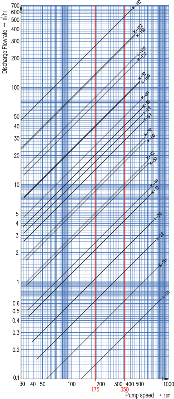
Performance graph and Model selection
In the graph below, , the horizontal axis indicates the rpm of the pumps, and the vertical axis indicates the discharge flow rate.Since the discharge volume of the mono pump is directly proportional to the number of rotations, the performance graph of each model are all displayed as straight lines.
Among the several models that can satisfy the required discharge flow rate on the graph, the pump is selected primarily by examining whether the rotation speed is within the proper speed rangefor the transfer liquid. The final decision is made in consideration of the need for speed variation and available reducer and speed variator.
How to read the graph
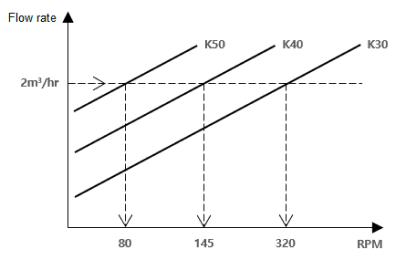
To obtain a pump with a capacity of 2m³/hr, find the 2m³/hr point on the vertical axis of the graph, move it horizontally, then you will find the intersections with each performance graph of K50, K40, K30.
You can see that the horizontal line of 2m³/hr intersects with K50 at 80rpm with K40 at 145rpm and with K30 at 320rpm. Among these models, if the concentration is very high, such as dewatered sludge, K50 is selected, if it is thin, K30 is selected, and if it is of medium concentration, K40 is selected.
1Performance graph for general models
2Performance graph for KL small-capacity models
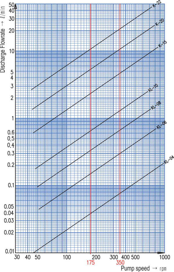
- The values in the graph above are for reference only
- The red line is the pump rotation speed of 350rpm(5:1) and 175rpm(10:1), when using commonly used motors (4 poles, 60Hz) and reducers (5:1, 10:1)