Drive Unit
After the pump type and operating speed are selected, a drive motor suitable for the pump is selected through the following process. Whether the discharge flow rate is to be constant? or is to be controlled
- 1. Discharge flow rate Constant or Variable
- 2. Determination of the horsepower
1Whether the discharge flow rate is to be constant? or is to be controlled as variable?
Whether the discharge flow rate should be constant or adjusted, determines whether the pump is of constant speed or variable speed, and an appropriate driving method is to be adopted accordingly.
A. Deceleration method when driving at constant speed
The allowable rotation speed of the pump (20-1200 rpm) is generally slower than the rotation speed of the 4-pole motor (1750 rpm at 60 Hz).
Therefore, by connecting a reduction device suitable for the drive motor, the pump speed can be reduced to the required speed.
For deceleration
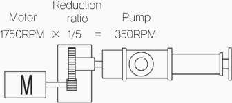
1. To use the reducer (Direct coupled in-line type)
- To use the standard reduction ratio of the reducer manufacturer, such as -5:1,10:1.
- In special cases, a custom decelerator can be used to match the specific reduction ratio required.
- Geared motors in which the motor and reducer are integrated, are often used.
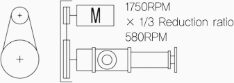
2. To use V-Belt Pulley (Overhead mounting, v-belt drive type)
- The reduction ratio can be adjusted by adjusting the size of the pulley, but the pulley becomes too large for a large reduction ratio, so use it within 6:1.
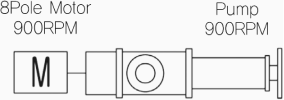
3. To use a multi-pole motor (Direct coupled in-line type or Overhead mounting v-belt drive type)
- The pump can be directly driven by using a low-speed multi-pole motor such as 6-pole (1200rpm) or 8-pole (900rpm), or various. rotational speeds can be obtained by applying a speed reducer or V-belt to the multi-pole motor.
B. Speed Variation and deceleration method for variable speed
If the discharge flow rate needs to be adjusted, first variate the speed of the motor and then decelerate in the same way as above A.
The way to variate the speed of rotation is
1. Using inverters (Direct coupled in-line type or Overhead mounting, v-belt drive type)
- Generally, inverters are used to control the speed of a motor by changing the frequency of the power supplied to the motor. After adjusting the speed of the motor, it is decelerated by a reducer(Direct coupled In-line type) or Vbelt (Overhead mounting, V-belt drive type) method.
For 4-pole motors
Motor speed
- 60Hz
- 1800rpm
Speed after inverter
deceleration
- 20Hz ~ 60Hz ~ 90Hz
- 600rpm ~ 1800rpm ~ 2700rpm
Pump speed
- 20Hz ~ 60Hz ~ 90Hz
- 120rpm ~ 360rpm ~ 540rpm
2. Using servo motors (Direct coupled in-line type)
- When a wide speed range and precise and flexible flow control is required, servo motors are used and usually speed reducers are directly connected.
- Multiple servo amplifiers can be connected through communication to control multiple units.
3. Others
- In the past, the method of using a mechanical variable speed reduction of the frictional principle or using a VS motor with V-belt pulley was used, but due to the development of inverters, it is rarely used these days
2Determination of the horsepower of the drive motor
- A. Calculate the required shaft power
- B. Calculate the motor capacity by multiplying the shaft power by the margin ratio.
- C. Compare the calculated capacity with the minimum shaft power and determine a value that exceeds this.
A.Formula to calculate the required shaft power
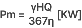
- Pm : Pump shaft power
- γ : Liquid specific gravity [kg/cm³]
- H : Pumping Head [m]
- Q : Flow rate [m³/h]
- η : Efficiency [0.5~0.8]
Efficiency is set higher as the pump is larger and the speed is higher.
B. Selection of the motor power

- P : Selected motor rated power
- α : Margin ratio 1.5~2.0
The margin ratio is determined by considering the speed change/deceleration method, starting device, operating conditions, mixing of foreign materials, viscosity of liquid, increase/decrease in concentration, and various abnormal conditions. Select in the range of 1.5 to 2.0 so that there is sufficient margin than the shaft power calculated by the above formula.
C. Minimum shaft power per model
| Model number | 15 | 20 | 30 | 40 | 50 | 60 | 69 | 80 | 89 | 100 | 120 | 150 |
|---|---|---|---|---|---|---|---|---|---|---|---|---|
| Minimum shaft power | 0.12 | 0.25 | 0.55 | 0.75 | 1.1 | 1.5 | 2.5 | 3.0 | 4.0 | 5.5 | 11 | 15 |
D. MONAS standard performance table
As mentioned above, since the efficiency and margin ratio of the pump are determined by reflecting our test results and field experiences, it is difficult for ordinary people to calculate them in consideration of these values. Please refer to the MONAS Standard Performance Table prepared in advance reflecting field experiences.
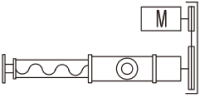
3Arrangement of the driver of the mono pump
- The assembly form of the driver of the mono pump depends on the deceleration method. When decelerating with a reducer, it is generally a Direct coupled In-line type, and when decelerating with a V-belt, it is usually an Overhead mounting, V-belt drive type, but the driver can be installed in various types depending on the site conditions.
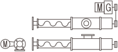
- In the case of the Overhead mounting, V-belt drive type, the suction port cannot be located at the top. In general, it is preferable to install the Direct Coupled in-line type.

Direct coupled
Overhead mounting
Side mounting
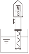
Vertical
4Driver other than motor
In addition to the electric motor, the following drivers may also be used.
- Engine : Mainly used for mobile equipment in the field where electric power supply is not available
- Hydraulic motor : When hydraulic pressure can be supplied from the existing hydraulic system, etc.